AMS Tester for testing the AMS functionality product photo Front View L
For a larger view click on the picture.

AMS Tester for testing the AMS functionality

555010
Compare

SPINNER Antenna Monitoring System - protect your broadcast infrastructure

All over the world radio and television broadcasters rely on their transmission systems operating unfailing around the clock, including patch panels, feeder cables and dipoles. The infrastructure itself is generally robust, but in the long run can be damaged and disturbed sustainable through RF overloads, incorrect installation or environmental influences (e.g.: UV radiation, ice, strong wind).

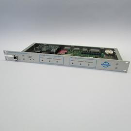
SPINNERs Antenna Monitoring System (AMS) was developed to detect and pinpoint potential malfunction sources, like minimal arcing, compromised insulation or water ingress as early as possible. Thus, the whole broadcast transmission system can be prevented from greater damages, for example degraded RF-components, fire or even a complete off-air situation. All conspicuous events are continuously and reliable recorded in the AMS control unit and can be checked from anywhere via a user-friendly web interface, which also can be used to easily configurate the AMS system setup. A detected failure triggers an alarm both locally on warning LEDs and remotely via a SNMP (Simple Network Management Protocol) interface.

All AMS system components are engineered for indoor installation and can be integrated simple and fast, even in already existing broadcast sites.

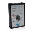
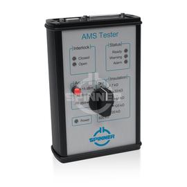
An AMS tester, which simulates arc and water ingress and is used to test the Antenna Monitoring System. The interlock system can also be tested.

The protection class is IP 40.

The positive characteristics are briefly summarised: Tests the function of the U-Link/ Line Section and the Control Unit, Simulates arcing and different insulation resistances with the intent to test AMS warnings and alarms, Checks operation of interlock and status relays, Easy operation with one single rotary switch.

Delivery scope: The delivery of the product contains the following items: AMS Tester, connection cable D-SUB 25 (interlock relay test, from control unit to test adaptor, length 2 m), connection cable D-SUB 9 (status relay test, from control unit to test adaptor, length 2 m), 2 x patch cords (4 mm connectors, length 1 m), 2 patch cord adaptors (4 mm socket to 2 mm plug), 9 V battery, case for tester and accessories, manual, data sheet

Benefits of the AMS

  • Distance-to-fault detection
  • Arcing detection
  • Water ingress detection
  • Continuous monitoring of the whole system
  • Local signaling by LEDs and status relays
  • Remote signaling via SNMP and web interface
  • Protection by integrating transmitter into interlock loop
  • No signal distortion
  • Compact design
  • Fast, easy installation
  • All components indoors
  • No invasive changes to the system
  • Suitable for pressurized lines
  • Works for antennas of any height

RF characteristics

Waveguide component type:
AMS tester

Electrical characteristics

Operating modes:
Selectable via rotary switch. Simulation of arc signals, simulation of insulation resistance, “OFF”
Local signaling:
Interlock signal indication:
2 x LEDs
• red LED = all contacts open
• green LED = all contacts closed
• red LED + green LED = some contacts open, some contacts closed

Status signal indication:
3 x LEDs
• red LED = alarm
• yellow LED = warning
• green LED = ready

ON indication:
• green LED = in operation

Battery monitoring:
• ON indication steady green if battery is charged
• ON indication flashing green if battery is discharged, battery must be changed immediately
Connection to interlock contacts of control unit:
D-SUB 25 female
Connection to status contacts of control unit:
D-SUB 9 female
Connection to U-link / line section:
2 x banana jacks (4 mm connector), banana jack “IC” connects to inner conductor, banana jack “OC” connects to outer conductor
Selectable insulation resistance:
4.7 kΩ
33 kΩ
68 kΩ
220 kΩ
820 kΩ
Accuracy of resistor:
± 3 %
Test signal for arcing:
Sine wave, 125 kHz, 50 Ω impedance
Selectable power level of arcing test signal:
+ 15 dBm @ 50 Ω
+ 5 dBm @ 50 Ω
-15 dBm @ 50 Ω
Accuracy of power level of arcing test signal:
± 1.5 dB
Battery supply:
9-Volt Zn-MnO2 (IEC 6LR61, ANSI/NEDA 1604A)
Battery lifetime, typ. / min.:
10h/ 5h @ QBat= 0.65Ah

Mechanical characteristics

Operating modes:
Selectable via rotary switch. Simulation of arc signals, simulation of insulation resistance, “OFF”
Housing material / coating:
aluminum-alloy
Degree of protection:
IP 40
Weight, approx.:
2.0 kg
Length:
380.0 mm
Width:
330.0 mm
Height:
110.0 mm

Environmental conditions

Operational conditions:
ETSI EN 300 019-4-3 V2.3.2 (2009-1) class 3.1 N
Operating temperature:
-10 to +45 °C
Relative humidity, max.:
95% (condensation not allowed)
Transport conditions:
ETSI EN 300 019-1-2 V2.1.4 (2009-1) class 2.2
Transport temperature range:
-25 to +70 °C
Transport rain, condensation, icing:
not allowed
Storage conditions:
ETSI EN 300 019-1-1 V2.1.4 (2009-1) class 1.2
Storage ambient temperature:
-10 to +45 °C
Storage rain, condensation, icing:
not allowed

Scope of delivery & accessories

Delivery scope:
AMS Tester, connection cable D-SUB 25 (interlock relay test, from control unit to test adaptor, length 2 m), connection cable D-SUB 9 (status relay test, from control unit to test adaptor, length 2 m), 2 x patch cords (4 mm connectors, length 1 m), 2 patch cord adaptors (4 mm socket to 2 mm plug), 9 V battery, case for tester and accessories, manual, data sheet

Further remarks

Remark:
• Tests the function of the U-Link/ Line Section and the Control Unit
• Simulates arcing and different insulation resistances with the intent to test AMS warnings and alarms
• Checks operation of interlock and status relays
• Easy operation with one single rotary switch
Footnote:
For further technical information see "Environmental Conditions for Broadcast Products" TD-00060
Customs tariff number:
90303370

Downloads

555010-DS.pdf

Product data sheet – 555010 – 555010-DS.pdf