Improve signal quality, avoid damage, optimise performance
Mobile radio installations are at risk from external influences such as overvoltages and induced DC voltages. Protective devices such as surge arresters and DC blocks are used to compensate for these influences. Both components must protect the connected equipment without interfering with normal operation. A DC block is a line component that separates direct current (DC) from high-frequency signals. They are used to prevent direct current from flowing into the signalling path, which could impair the signal quality.
Types with open inner and outer conductor: They are mainly used for preventing undesirable induced voltage, in communication equipment, e.g. radiating cables. Inducted voltages are generated by e.g. high-power lines in underground train systems.
Types with open inner conductor only: They are mainly used for shielding antennas or ground stations from low-frequency signals deliberately fed in for controlling mobile communication antennas or for the power supply of tower mounted amplifiers.
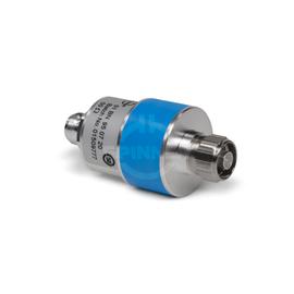
The Coaxial DC-Break N male N female IP67 80-3800 MHz inner/outer conductor separated guarantees excellent, lossless mobile communication quality for use in in-building distributed antenna systems (DAS) or on mobile communication base stations outdoors.
Outstanding RF characteristics, best possible passive intermodulation and VSWR
The Coaxial DC-Break N male N female IP67 80-3800 MHz inner/outer conductor separated enables you to transmit high-frequency signals reliably and flawlessly with optimum protection of your sensitive equipment in a power range up to 1500 W with maximum passive intermodulation (IM3) of -155 dBc. The protection class is IP 67.
The DC block also impresses with its technical values. The maximum insertion loss is 0.25 dB @ 80 to 3800 MHz . The blocking of the DC voltage is 3000 V (outer to outer conductor, for VSWR=1.0 at sea level, ambient temperature 20 °C)
3000 V (inner to inner conductor, for VSWR=1.0 at sea level, ambient temperature 20 °C). The connector has a straight direction.
The N-coaxial connectors were named after their inventor Paul Neill, who developed this standard for RF connectors in 1942. Often, however, the name also relates to the Navy Connector. Type N connectors can be used at frequencies up to 11 GHz, high-precision types up to 18 GHz. It is typically used in mobile communication applications with demanding mechanical and electrical requirements. SPINNER exclusively manufactures connectors with non-slotted outer conductor contacts and a special sealing profile in the connector head instead of the flat seal disk, specified by IEC or CECC. This ensures the most reliable sealing function.
The product offers a transition from interface N male to interface N female.
Benefits of SPINNER DC breaks for your mobile radio network
- Ensure signal integrity: The DC block separates direct current from high-frequency signals, improving signal quality and integrity. This is crucial for reliable communication in mobile networks.
- Protection against damage: By isolating direct current, engineers can ensure that radio frequency circuits are not damaged by unwanted current. This helps to extend the life of the infrastructure.
- Improved performance: A clean radio frequency signal, free from DC, can improve the performance of mobile devices and networks, resulting in better transmission quality and higher network performance.
- Compatibility and reliability: The specific DC block is equipped with interfaces commonly used in cellular applications. The robust design and protection class make it robust and reliable, even in demanding outdoor and tunnel environments.