High-Performance Directional Couplers for radio frequency networks
A directional coupler is a passive component used in radio frequency (RF) systems to split or combine RF signals while maintaining the directional flow of the signal. Its primary function is to transfer a portion of the RF power flowing in one transmission line to another transmission line, typically with minimal loss.
Directional couplers operate based on the principle of electromagnetic coupling between transmission lines. They consist of at least four ports: the input port (usually called the main line), the output port (also known as the through port), and two auxiliary ports (the coupled port and the isolated port.
When an RF signal is applied to the input port, a portion of that signal is coupled to the coupled port while the majority of the signal continues through to the output port. The amount of power coupled to the auxiliary port is determined by the design of the directional coupler and is typically specified as a coupling factor in decibels (dB).
Directional couplers are essential components in broadcast stations or mobile communication networks. Couplers enable engineers to monitor signal strength, analyse performance, and distribute signals to various components within the broadcast or communication system. Use cases are:
- Signal Monitoring: Directional couplers allow RF engineers to monitor signal strength and quality at various points within the RF system, ensuring optimal performance.
- Signal Measurement: They facilitate accurate measurement of RF signals for troubleshooting, maintenance, and performance optimization.
- Signal Distribution: Directional couplers enable the distribution of RF signals to multiple components or devices within the transmission line without significant signal loss.
- Isolation: They provide isolation between the input and output ports, minimizing interference and ensuring signal integrity.
- Versatility: SPINNER directional couplers are available in various designs and frequency ranges, making them suitable for a wide range of broadcast or mobile communication system applications.
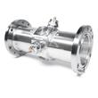
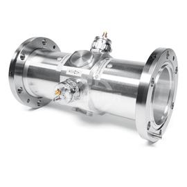
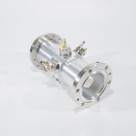
The Directional coupler 40-860 MHz 3 1/8" EIA female with 2 probes SMA female ensures optimal performance for signal transmission between transmitter and antenna in broadcast stations.
SPINNER directional couplers are characterized by highly effective signal isolation and extremely low intermodulation (low PIM).
Our Directional coupler 40-860 MHz 3 1/8" EIA female with 2 probes SMA female is meticulously engineered to meet the demanding requirements of high performance RF systems. Designed and built with precision and versatility in mind, these directional couplers offer unparalleled performance for RF engineers building full broadcast systems or install mobile communication networks.
Key Features:
- Accurate signal monitoring and measurement capabilities
- High-quality construction for long-term reliability
- Wide frequency range to accommodate diverse broadcast or mobile communication system needs
- Excellent signal isolation to minimize interference
- Easy integration into existing broadcast or mobile communication setups
- Robust design suitable for demanding broadcast or mobile communication environments
Outstanding RF characteristics, best possible passive intermodulation and VSWR
The Directional coupler 40-860 MHz 3 1/8" EIA female with 2 probes SMA female enables you to transmit high-frequency signals reliably and flawlessly with optimum protection of your sensitive equipment in a power range up to 67 kW @ 100 MHz, 44 kW @ 230 MHz, 23 kW @ 860 MHz 1) with maximum passive intermodulation (IM3) of .
The port path designation regarding main line and probe is as follows: Port 1, 2: main line, Port 3, 4: probe
It supports the use following frequency bands : Band 1, Band 2, Band 3, Band 4/5
The positive characteristics are briefly summarised: extremely compact design, suitable in a wide frequency range, variable coupling, low VSWR, high directivity, for indoor application, termination load is included.
Coaxial flange connectors, generally known as “EIA flanges”, are connected by a coupling element. The flange connector system complies with international standards EIA STD RS-225, 339 IEC, DIN EN 122150 and MIL-F 24044. The EIA flange connectors are excellently qualified suited for pressurized systems and for outdoor installations. 3 1/8" EIA connectors are used to link two elements of a rigid or semi-rigid high performance coaxial transmission line for radio frequency signals. Typically, these are operated in systems for very high power transmission (from kW to MW), e.g. in DAB, DVB or FM broadcast systems or in high-energy applications in research facilities (particle accelerator, plasmatron).
The product offers a transition from interface 3 1/8" EIA female to interface 3 1/8" EIA female.
Invest in our high-performance directional couplers to elevate the performance and reliability of your broadcast or mobile communication system. Trust in our expertise and commitment to delivering superior RF components for your broadcasting needs. Overall, this directional coupler offers a simple and cost-effective solution for your installation.