High-Performance Directional Couplers for radio frequency networks
A directional coupler is a passive component used in radio frequency (RF) systems to split or combine RF signals while maintaining the directional flow of the signal. Its primary function is to transfer a portion of the RF power flowing in one transmission line to another transmission line, typically with minimal loss.
Directional couplers operate based on the principle of electromagnetic coupling between transmission lines. They consist of at least four ports: the input port (usually called the main line), the output port (also known as the through port), and two auxiliary ports (the coupled port and the isolated port.
When an RF signal is applied to the input port, a portion of that signal is coupled to the coupled port while the majority of the signal continues through to the output port. The amount of power coupled to the auxiliary port is determined by the design of the directional coupler and is typically specified as a coupling factor in decibels (dB).
Directional couplers are essential components in broadcast stations or mobile communication networks. Couplers enable engineers to monitor signal strength, analyse performance, and distribute signals to various components within the broadcast or communication system. Use cases are:
- Signal Monitoring: Directional couplers allow RF engineers to monitor signal strength and quality at various points within the RF system, ensuring optimal performance.
- Signal Measurement: They facilitate accurate measurement of RF signals for troubleshooting, maintenance, and performance optimization.
- Signal Distribution: Directional couplers enable the distribution of RF signals to multiple components or devices within the transmission line without significant signal loss.
- Isolation: They provide isolation between the input and output ports, minimizing interference and ensuring signal integrity.
- Versatility: SPINNER directional couplers are available in various designs and frequency ranges, making them suitable for a wide range of broadcast or mobile communication system applications.
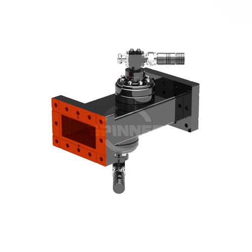
The Directional coupler 2 probes R 32 DESY N female is characterized by low intermodulation and its longevity for test and measurement laboratories. A SPINNER precision adapter increases the lifetime of the connector of the analyzer considerably and thus saves money in the long term.
Outstanding RF characteristics, best possible passive intermodulation and VSWR
The Directional coupler 2 probes R 32 DESY N female enables you to transmit high-frequency signals reliably and flawlessly with optimum protection of your sensitive equipment in a power range up to 400 W with maximum passive intermodulation (IM3) of .
The port path designation regarding main line and probe is as follows: Port 1, 2: main line, Port 3, 4: probe
For interconnection of ordinary waveguides there exists a plurality of waveguide flanges. They are defined in detail by the standards IEC 60154-2, EIA RS-166, EIA RS-271, MIL-DTL-3922, MOD UK DEF-5352and others. These standards also specify the designations for the constructive flange design. The designation lists the type, e.g. flat flange without sealing groove, flat flange with sealing groove or choke flange with sealing groove. Furthermore, the types, i.e. the specific flange geometry (as in EIA and IEC standards) or the part number of a specific flange made of a specific material (as in MIL and DEF standards) are indicated. Finally, the designation of the waveguide is given.
For the specific details, please refer to the SPINNER technical document TD-00077. In addition to these standardized flange designs, there are other specific designs such as LIL (CERN), DESY or Merdinian. The compatibility is indicated in the data sheets.
Invest in our high-performance directional couplers to elevate the performance and reliability of your broadcast or mobile communication system. Trust in our expertise and commitment to delivering superior RF components for your broadcasting needs. Overall, this directional coupler offers a simple and cost-effective solution for your installation.

