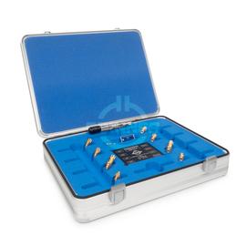
Precision Calibration Kits - all necessary calibration standards in one sturdy case
Nowadays, no development, production, testing, or quality control department that deals with RF signals on coaxial lines can afford to dispense with state-of-the-art high-precision equipment. It’s essential to use vector network analyzers (VNAs) in particular with high-precision connectors, terminations, and adapters.
Systematic errors can be fixed by calibrating the VNA. Different calibration standards with defined and known electrical characteristics are applied and compared to identify error coefficients. A technique called vector error correction is used to characterize error terms while applying known standards in order to remove errors from actual measurements and increase the accuracy of the results.
A VNA can be calibrated in different ways depending on the required degree of accuracy. The methods used differ in both the number and the type of the calibration standards applied.
The most commonly used calibration approaches are OSL (which stands for open-short-load) for single-port measurements and OSLT (for open-short-load-through) for multiple-port measurements. The order of the standards can vary in the designation; for example, the abbreviation SOLT is occasionally used synonymously.
OSLT precision calibration kits are used worldwide for High-end S-parameter measurements for the development of RF components for mobile communication, broadcast, radar applications, satellite communication, automotive engineering and manufacturing, mechanical engineering and many other industrial applications.
The OSLT calibration kit 1.35 mm male 1.35 mm female offers the combination of all necessary calibration standards in one robust aluminum case. It is the optimal and high quality solution for a convenient and complete calibration of a network analyser with two or more ports using the OSLT procedure with the calibration standards open circuits (O, open), short circuits (S, short), fixed loads (L, load) and through adapters (T, through). Each one is provided in male and female version including through adapters, one with male-to-male and one with female-to-female connections. Optionally a male-to-female is available. Calibration data in digital formats for common VNAs are included on a USB-stick in the kit. It includes individual calibration coefficients determined during manufacture for every kit to achieve the best possible accuracy.
The OSLT calibration kit 1.35 mm male 1.35 mm female has a characteristic impedance of 50 Ω. It is characterised by very low VSWR and attenuation values as well as best intermodulation properties in the entire operating frequency range from DC to 90 GHz.
This product has gold-plated connections and is based on the better quality classes of the IEEE, ICE standards with regard to lower tolerances. SPINNER also uses the term ‘precision’ here to emphasize the suitability for exceptionally high-precision measurements.
The SPINNER 1.35 mm connector is the best high-precision coaxial connector for E-band applications, a robust precision interface for DC up to 90 GHz. Especially in E-band applications, reliable coaxial interface connections are crucial for achieving good RF performance.
The suggested initial interval for recalibration is 12 months or 500 mating’s, whichever comes first. The actual need for recalibration depends on the use and the maintenance of the kit. The recalibration interval should begin with the day of initial use after recalibration.
SPINNER RF measurement components meet highest standards
SPINNER has set new standards of accuracy with this product line, which includes a large family of coaxial test equipment with outstanding electrical and mechanical attributes for use in laboratory and production environments.
For the production SPINNER applies extremely high standards regarding quality, engineering, materials and manufacturing e.g. DIN EN ISO 9001 - Quality Management, DIN EN ISO 14001 - Environmental Management and ISO 50001:2011 - Energy Management. This enables us to offer precision calibration kits with the best possible performance and lowest possible intermodulation (Low PIM).