RF Switches with outstanding performance
A radio frequency (RF) switch plays a critical role in routing signals between different paths within the RF circuitry. Here’s a detailed breakdown of its function and importance:
- Signal Routing: RF switches enable the selection of different signal paths within a communication system. This routing function is essential for directing RF signals from one component to another, such as from a transmitter to an antenna or between different antenna elements.
- Frequency Band Selection: In mobile communication networks, RF switches allow the selection of different frequency bands. This capability is crucial for supporting multiple standards (e.g., GSM, LTE, 5G) and frequency bands in a single device. By switching between different frequency bands, a device can operate across various cellular networks and frequencies
- Antenna Switching: RF switches are used to switch between multiple antennas. For instance, in MIMO (Multiple Input Multiple Output) systems, RF switches manage the connections to different antennas to optimize signal strength and quality.
- Transmit/Receive (T/R) Switching: In transceivers, RF switches facilitate the switching between transmit and receive modes. This function is vital for time-division duplex (TDD) systems where the same frequency band is used for both transmitting and receiving but at different times.
- Redundancy and Fault Tolerance: In broadcasting systems, RF switches provide redundancy by switching to backup components or paths in case of failure. This ensures continuous operation and reliability of the communication system.
- Signal Testing and Monitoring: RF switches are often used in test and measurement setups to route signals to different test points or instruments without manually reconnecting cables. This allows for efficient and automated testing and monitoring of RF performance.
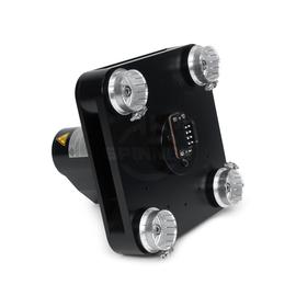
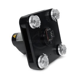
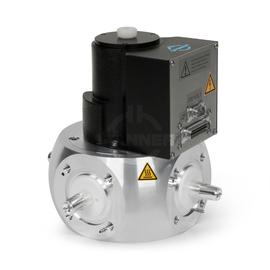
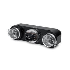
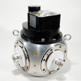
The Parallel switching unit 2 x 3.5 kW 1 5/8" USL-D ensures optimal performance for signal transmission between transmitter and antenna in broadcast stations.
This patch panel has been designed for use with interlock type IL-1 with 4 loops. This component ensures safety during signal switching between different transmission lines. The Il-1-4 interlock type ensures that the transmitter is turned off during the switchover to prevent accidental interference or damage to equipment. It plays a vital role in maintaining safety, signal integrity, and efficient operation in broadcasting and communication systems. Il-1 helps manage signal routing efficiently.
The patch panel has 4 interlock contacts.
Outstanding RF characteristics, best possible passive intermodulation and VSWR
The Parallel switching unit 2 x 3.5 kW 1 5/8" USL-D enables you to transmit high-frequency signals reliably and flawlessly with optimum protection of your sensitive equipment in a power range up to 3.5 kW (per port) with maximum passive intermodulation (IM3).
It supports the use of the following frequency bands : Band 4/5
The positive characteristics are briefly summarised: operation with U-links or motorized switches (see options), motorized switches with control voltage 8-31VDC or 230 VAC are available, integrated balancing load, interlock contacts and position signal contacts supplied, measurement port.
Coaxial flange connectors, generally known as “EIA flanges”, are connected by a coupling element. The flange connector system complies with international standards EIA STD RS-225, 339 IEC, DIN EN 122150 and MIL-F 24044. The EIA flange connectors are excellently qualified suited for pressurized systems and for outdoor installations. 1 5/8" EIA connectors are used to link two elements of a rigid or semi-rigid high performance coaxial transmission line for radio frequency signals. Typically, these are operated in systems for very high power transmission (from kW to MW), e.g. in DAB, DVB or FM broadcast systems or in high-energy applications in research facilities (particle accelerator, plasmatron).
Parallel switching units are used to double the output power by combining two transmitters that operate at the same frequency and have a phase differential of 90°.
Typically, the failure of one transmitter will cause the output power to drop by 75% because half of the power from the working transmitter then flows into the balancing load of the coupler.
The SPINNER parallel switching unit can route transmitter 1 or transmitter 2 straight to the antenna and transmitter 2 or transmitter 1 to the dummy load within seconds. As a result, 50% of the original output power then once again becomes available and the disconnected transmitter is freed for repair or maintenance work. The combined output of both transmitters can also be routed to the dummy load for measurements.
Switching is done by remotely controlled, motorized two-way switches. In an emergency, the switches can also be operated manually or replaced by U-links. Interlock contacts are available in all cases.
- Standard operation: transmitters TX1 and TX2 to antenna, measuring port to dummy load
- Emergency operation: working transmitter to antenna, defective transmitter to dummy load for measurement or repair
- Testing: transmitters TX1 and TX2 to dummy load, measuring port to antenna