SPINNER Combining Units for best radio frequency networks performance
Combining units are essential components in radio frequency networks, used to merge signals from multiple sources or split signals into multiple paths while maintaining signal integrity. All combiners work in bi-directional mode and can therefore be used to combine and split the transmitted and received signals.
The 2-way CIB combiner band 4/5 DTV 4 kW WB input 750 W NB input without front plate ensures optimal performance for signal transmission between transmitter and antenna in broadcast stations.
In broadcast applications multi-channel combiners are used to combine the signals of two or several channels on to one antenna. SPINNER combiners stand out for their low VSWR, low insertion loss, high isolation between the inputs, compact design and easy installation. SPINNER frequency combiners are used world-wide, and since they are so reliable and maintenance-free they regularly exceed the high expectations that our customers have of SPINNER products.
A Constant Impedance Broadband (CIB) combining unit is designed to manage and equalize the impedance levels across multiple channels in a broadcast system. This ensures that the system maintains high efficiency by minimizing signal reflections and losses due to impedance mismatches. Such units are vital in complex network architectures where uniform signal propagation and integrity are critical for reliable and stable transmission. It allows multiple transmitters or receivers to share a common antenna feeder cable or antenna.
CIB combiners are mainly used when the channels are close together or when retuning is required. Even adjacent channel or adjacent block operation and the combination with starpoint and stretchline combiners at a later point in time are possible.
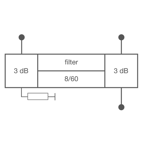
Good isolation, broadband matching and easy modification can be achieved in the CIB combiner with a combination of bandpass filters and 3 dB couplers. The signal applied to the narrowband input is fed via the narrowband 3 dB coupler into the two bandpass filters, then recombined afterwards in the wideband 3 dB coupler and routed to the antenna output. The signals fed into the wideband input arrive at the filter ports via the wideband 3 dB coupler, which totally reflects them back to the wideband coupler. They are then routed to the antenna output. All of the ports are broadband-matched (yielding constant impedance across a broad band). Any transmitter signal can be fed into the wide-band input as long as the frequency spacing across the filters’ passband range is large enough to ensure total reflection. Even adjacent channels can be combined if the slopes of the filter curves are steep enough. CIB combiners are the preferred components for designing multichannel combiners because they provide the greatest flexibility for configuring channels and power levels.
Outstanding RF characteristics, best possible passive intermodulation and VSWR
The 2-way CIB combiner band 4/5 DTV 4 kW WB input 750 W NB input without front plate enables you to transmit high-frequency signals reliably and flawlessly with optimum protection of your sensitive equipment in a power range up to 750 W @ 8 MHz with maximum passive intermodulation (IM3).
The port path designation regarding main line and probe is as follows: Port 1: narrow band input, Port 2: wide band input, Port 3: output
It supports the use of the following frequency bands : Band 4/5
The positive characteristics are briefly summarised: Compact design as 19" slide-in unit , For 6, 7 and 8 MHz channel bandwidth, Integrated mask filters for DTV, Adjacent channel operation, Temperature compensated, Tunable within the whole UHF range.
The 7-16 connector has become the most widely used coaxial connection system for mobile communication systems, due to its excellent mechanical and electrical properties. In order to achieve the industry leading intermodulation performance SPINNER applies silver-plating on all inner and outer conductor parts of the standard connector. As a supporting measure, we use exclusively non-magnetic materials, and we have minimized the number of RF contact points. The connection is especially suited for transmitting medium or high power indoors and outdoors.
The product offers a transition from interface 7-16 female to interface 1 5/8" SMS unflanged.


