SPINNER Combining Units for best radio frequency networks performance
Combining units are essential components in radio frequency networks, used to merge signals from multiple sources or split signals into multiple paths while maintaining signal integrity. All combiners work in bi-directional mode and can therefore be used to combine and split the transmitted and received signals.
The 2-way manifold combiner band 4/5 DTV 7 kW output power 1.6 kW NB input ensures optimal performance for signal transmission between transmitter and antenna in broadcast stations.
A manifold combiner is a device designed to combine multiple input signals into a single output. This is particularly useful in environments where space efficiency and signal integrity are paramount. Manifold combiners are used to streamline the handling of signals from different sources, facilitating a cleaner and more efficient distribution of signals within the network infrastructure. This makes them essential for complex systems where multiple channels need to be managed effectively and without interference.
Manifold combiners are usually designed as 2- or 3-way combiners and require a minimum spacing of one channel or one DAB block in between.
SPINNER’s Manifold Combiners excel in reliability, performance, and adaptability. Our products are recommended because they provide a flexible solution for both indoor and outdoor mobile communication networks. Whether enhancing in-
building coverage or expanding network capacity, SPINNER’s Manifold Combiners offer a reliable backbone for seamless wireless communication.
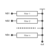
Transmitters can be isolated from each other by connecting a bandpass filter to each output. To achieve good matching for the operating channels, the outputs of these filters must be connected via a suitable matching network.
Frequency changes or extensions are difficult to accomplish with combiners of these kinds because the matching networks have to be optimized for the new frequencies.
Outstanding RF characteristics, best possible passive intermodulation and VSWR
The 2-way manifold combiner band 4/5 DTV 7 kW output power 1.6 kW NB input enables you to transmit high-frequency signals reliably and flawlessly with optimum protection of your sensitive equipment in a power range up to 1.6 kW @ 8 MHz (per input for non-adjacent channels or 1.2 kW for adjacent channels) with maximum passive intermodulation (IM3).
The port path designation regarding main line and probe is as follows: Port 1, 2: narrow band input, Port 3: output
It supports the use of the following frequency bands : Band 4/5
The positive characteristics are briefly summarised: Compact design as 19" slide-in unit (7RU per channel), Delivered in rack, Installation in customer-owned rack on request, Integrated mask filters for DTV, Applicable within the whole UHF range, For 6, 7 and 8 MHz channel bandwidth, Temperature compensated.
Coaxial flange connectors, generally known as “EIA flanges”, are connected by a coupling element. The flange connector system complies with international standards EIA STD RS-225, 339 IEC, DIN EN 122150 and MIL-F 24044. The EIA flange connectors are excellently qualified suited for pressurized systems and for outdoor installations. 1 5/8" EIA connectors are used to link two elements of a rigid or semi-rigid high performance coaxial transmission line for radio frequency signals. Typically, these are operated in systems for very high power transmission (from kW to MW), e.g. in DAB, DVB or FM broadcast systems or in high-energy applications in research facilities (particle accelerator, plasmatron).