SPINNER patch panels for highest reliability
Patch panels are used for routing transmitter signals to single, half, backup antennas, or dummy loads or for bypassing intermediate systems such as combiners or splitters. They allow for the quick and flexible connection, re-routing, or disconnection of different signal paths. Critical features include
- precise and performant interfaces and components for high signal integrity,
- robust construction protecting the components from physical damage and electromagnetic interference and
- clear labeling for easy identification.
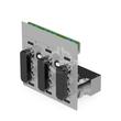
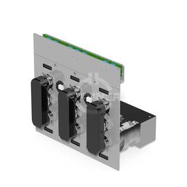
The 6-port patch panel 170-240 MHz 1 5/8" USL-D 1 5/8" EIA IL-1-4 ensures optimal performance for signal transmission between transmitter and antenna in broadcast stations.
This patch panel has been designed for use with interlock type IL-1 with 4 loops. This component ensures safety during signal switching between different transmission lines. The Il-1-4 interlock type ensures that the transmitter is turned off during the switchover to prevent accidental interference or damage to equipment. It plays a vital role in maintaining safety, signal integrity, and efficient operation in broadcasting and communication systems. Il-1 helps manage signal routing efficiently.
The patch panel has 4 interlock contacts.
Outstanding RF characteristics, best possible passive intermodulation and VSWR
The 6-port patch panel 170-240 MHz 1 5/8" USL-D 1 5/8" EIA IL-1-4 enables you to transmit high-frequency signals reliably and flawlessly with optimum protection of your sensitive equipment in a power range up to 13.5 kW with maximum passive intermodulation (IM3).
It supports the use of the following frequency bands : Band 3
The positive characteristics are briefly summarised: 19" front panel, access to the interlock terminal strip provided at the front, symmetrical power splitter included, U-links with interlock system 1 (IL 1-4), measurement at the front possible.
The product offers a transition from interface 1 5/8" USL-D to interface 1 5/8" USL-D.
SPINNER patch panels are the most reliable of their kind available on the market. They include micro-strip contacts to guarantee a perfect connection even after repeated operations. They are easy to handle and do not need any extra tools for installation.
The switchover can be carried out with motor switches or manually with U-links. All patch panels have an interlock system that switches off the transmitter during the switchover.
All input / output connectors are ending horizontal with EIA flange system behind the front panel.
The systems connected to the patch panel can be measured easily, quickly and precisely using measuring adapters.