SPINNER Filters offer reliability, performance, and value
Radio Frequency (RF) filters are crucial components in mobile communication and broadcast networks. Their primary function is to selectively allow signals of certain frequencies to pass while blocking others, thereby managing interference and enhancing the clarity and quality of the transmission. Applications include cellular base stations, broadcasting, and other RF communication systems.
Critical Characteristics and Success Factors:
- Selectivity: The ability to precisely isolate specific frequency bands.
- Insertion Loss: Minimal loss of signal strength through the filter.
- Power Handling: Capability to manage the power level of the signal without degradation.
- Durability: Performance consistency over a range of environmental conditions.
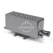
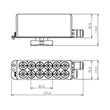
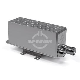
The Band-stop filter 900 MHz 10 W 7-16 female guarantees excellent, lossless mobile communication quality for use in in-building distributed antenna systems (DAS) or on mobile communication base stations outdoors.
Band-stop filtes are used to protect against specific interference by rejecting a particular frequency range while allowing all others to pass. Ideal in environments where specific frequency bands are known to cause disruption.
Outstanding RF characteristics, best possible passive intermodulation and VSWR
The Band-stop filter 900 MHz 10 W 7-16 female enables you to transmit high-frequency signals reliably and flawlessly with optimum protection of your sensitive equipment in a power range up to 10 W with maximum passive intermodulation (IM3) of -130 dBc.
The protection class is IP 65.
It supports the use of the following frequency bands : 900
The 7-16 connector has become the most widely used coaxial connection system for mobile communication systems, due to its excellent mechanical and electrical properties. In order to achieve the industry leading intermodulation performance SPINNER applies silver-plating on all inner and outer conductor parts of the standard connector. As a supporting measure, we use exclusively non-magnetic materials, and we have minimized the number of RF contact points. The connection is especially suited for transmitting medium or high power indoors and outdoors.
Our RF filters are engineered with precision, offering exceptional selectivity and low insertion loss, which are critical for efficient RF communication. Our range includes filters designed for various specific applications, ensuring that whatever your needs, we have a filter that fits. With robust construction, our filters maintain performance across a broad range of environmental conditions, making them ideal for both mobile communication and broadcast networks.
Our unique approach to RF filter design combines innovative technology with practical application insights, resulting in products that not only meet but exceed industry standards. For anyone involved in the construction or operations of RF mobile communication or broadcast networks, our filters offer reliability, performance, and value.