RF Switches with outstanding performance
A radio frequency (RF) switch plays a critical role in routing signals between different paths within the RF circuitry. Here’s a detailed breakdown of its function and importance:
- Signal Routing: RF switches enable the selection of different signal paths within a communication system. This routing function is essential for directing RF signals from one component to another, such as from a transmitter to an antenna or between different antenna elements.
- Frequency Band Selection: In mobile communication networks, RF switches allow the selection of different frequency bands. This capability is crucial for supporting multiple standards (e.g., GSM, LTE, 5G) and frequency bands in a single device. By switching between different frequency bands, a device can operate across various cellular networks and frequencies
- Antenna Switching: RF switches are used to switch between multiple antennas. For instance, in MIMO (Multiple Input Multiple Output) systems, RF switches manage the connections to different antennas to optimize signal strength and quality.
- Transmit/Receive (T/R) Switching: In transceivers, RF switches facilitate the switching between transmit and receive modes. This function is vital for time-division duplex (TDD) systems where the same frequency band is used for both transmitting and receiving but at different times.
- Redundancy and Fault Tolerance: In broadcasting systems, RF switches provide redundancy by switching to backup components or paths in case of failure. This ensures continuous operation and reliability of the communication system.
- Signal Testing and Monitoring: RF switches are often used in test and measurement setups to route signals to different test points or instruments without manually reconnecting cables. This allows for efficient and automated testing and monitoring of RF performance.
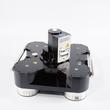
The Coaxial 2-way plug-in switch (DPDT) 82 kW DC-860 MHz 230 VAC 43-98 USL-D ensures optimal performance for signal transmission between transmitter and antenna in broadcast stations.
Outstanding RF characteristics, best possible passive intermodulation and VSWR
The Coaxial 2-way plug-in switch (DPDT) 82 kW DC-860 MHz 230 VAC 43-98 USL-D enables you to transmit high-frequency signals reliably and flawlessly with optimum protection of your sensitive equipment in a power range up to 82 kW @ DC to 100 MHz, 42 kW @ 100 to 230 MHz, 28 kW @ 230 to 860 MHz with maximum passive intermodulation (IM3).
The protection class is IP 40.
Coaxial 2-way plug-in switches are designed to be mounted on patch panels prepared with the required control interface with a suitable mating connector.
A motor drive, latching, self-cutoff actuator in a radio frequency (RF) switch operates as follows:
- Motor Activation: Motorized switches are turned by a special gear mechanism developed by SPINNER. This drive system rotates by 90° and locks in both end positions.
- Latching Mechanism: Once the switch reaches the intended position, a latching mechanism holds it in place.
- Self-Cutoff: The motor automatically shuts off after the switch is latched, preventing unnecessary power consumption and avoiding motor overheating.
This setup ensures precise and efficient switching with reliable position maintenance without continuous power.
A Double Pole Double Throw (DPDT) switch is an electrical switch that can control two separate circuits, allowing each to connect to one of two outputs. Essentially, it has two poles (each pole is a separate circuit) and two throws (two different output positions for each pole). This configuration enables the switch to route each input to one of two outputs, providing versatility in circuit control. DPDT switches are commonly used in applications requiring polarity reversal or the ability to switch between two different power sources.