SERIFLEX for indoor and housing interior installation
SERIFLEX cables are designed for indoor and housing interior installation and guarantee protection rating IP50 under standard IEC 60529. They also meet the RoHS 2002/95 guideline.
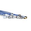
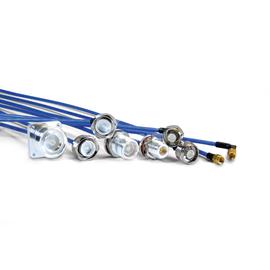
A coaxial jumper cable assembly SX 141-50-FEP N female NEX10® male screw 1.5 m is manufactured with an outer conductor made of lead-free tin-plated copper mesh. This selection of materials allows you to permanently bend the cable as desired with the cable retaining its shape and its RF properties.
Outstanding IM characteristics with maximum passive intermodulation
A SPINNER coaxial jumper cable assembly SX 141-50-FEP N female NEX10® male screw 1.5 m guarantees outstanding IM characteristics with maximum passive intermodulation (IM3) of -150 dBc (typ.) and low VSWR values over the entire frequency range and during the entire operating time of the cable. The robust construction defies even harsh outdoor conditions and for a temperature range from -55 to +85 °C. SPINNER coaxial cable assemblies comply with the RoHS 2002/95 Directive. The length of the cable is 1.5 m. The rugged coaxial cable has inner conductors made of copper, a PE dielectric insulation and a copper outer conductor. Inner and outer conductors are soldered 360° inductively. The degree of protection IP68 according to IEC 60529 is guaranteed.
On one end there is a N female connector pre-assembled, on the other end there is a NEX10® male screw connector. Thus, you can use the cable as an adapter for the transition between N and NEX10® connector systems.
The N-coaxial connectors were named after their inventor Paul Neill, who developed this standard for RF connectors in 1942. Often, however, the name also relates to the Navy Connector. Type N connectors can be used at frequencies up to 11 GHz, high-precision types up to 18 GHz. It is typically used in mobile communication applications with demanding mechanical and electrical requirements. SPINNER exclusively manufactures connectors with non-slotted outer conductor contacts and a special sealing profile in the connector head instead of the flat seal disk, specified by IEC or CECC. This ensures the most reliable sealing function.
Antenna and radio units for small cell applications are steadily shrinking, so it makes sense to also create ever-smaller connector systems for them. Designed to excellently meet the mechanical and electrical needs of small cell products, the new NEX10® is now conquering the market.
The screw connection, especially when mounted with a suitable torque wrench, provides the strongest hold and a constantly secure fit of the cable. In addition, the center slots in the contacts provide high contact pressure between the cable and the connector for optimum conductivity and signal strength.