LRL-Calibration Kits - High error compensation, precise measurement
Nowadays, no development, production, testing, or quality control department that deals with RF signals on coaxial lines can afford to dispense with state-of-the-art high-precision equipment. It’s essential to use vector network analyzers (VNAs) in particular with high-precision connectors, terminations, and adapters.
Systematic errors can be fixed by calibrating the VNA. Different calibration standards with defined and known electrical characteristics are applied and compared to identify error coefficients. A technique called vector error correction is used to characterize error terms while applying known standards in order to remove errors from actual measurements and increase the accuracy of the results.
A VNA can be calibrated in different ways depending on the required degree of accuracy. The methods used differ in both the number and the type of the calibration standards applied.
Calibration according to the so-called LRL (Line, Reflect, Line) method offers better error compensation possibilities and is currently the most accurate measuring method on the measuring equipment market. Ideally, two reflection-free precision airline impedance standards (Lines) of different lengths and two short circuits (Reflects) with the same complex reflection factors are used as calibration elements for the LRL method.
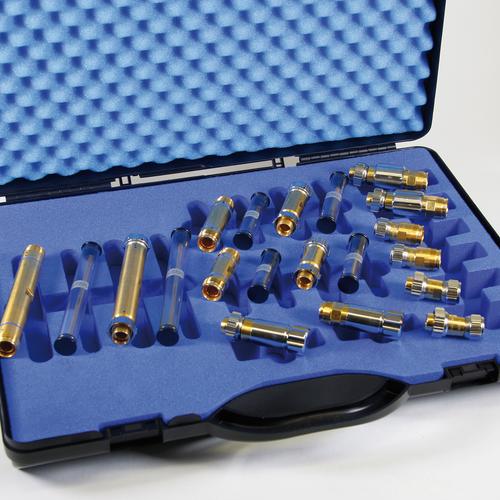
The LRL Calibration Kit DC-12 GHz 4.3-10 has a characteristic impedance of 50 Ω. It is characterized by very high precision and accuracy over the entire operating frequency range from DC to 12 GHz. The kit comes kept safe in a robust storage case.
This product has gold-plated connections and is based on the better quality classes of the IEEE, ICE standards with regard to lower tolerances. SPINNER also uses the term ‘precision’ here to emphasize the suitability for exceptionally high-precision measurements.
The 4.3-10 connector system was designed to meet the latest requirements in mobile communication in terms of size, robustness, performance, and other parameters. Its small footprint supports the use of smaller components, mitigates risks if equipment is assembled without due care, and delivers outstanding electrical performance.
The screw connection, especially when mounted with a suitable torque wrench, provides the strongest hold and a constantly secure fit of the cable. In addition, the center slots in the contacts provide high contact pressure between the cable and the connector for optimum conductivity and signal strength.
SPINNER RF measurement components meet highest standards
SPINNER has set new standards of accuracy with this product line, which includes a large family of coaxial test equipment with outstanding electrical and mechanical attributes for use in laboratory and production environments.
For the production SPINNER applies extremely high standards regarding quality, engineering, materials and manufacturing e.g. DIN EN ISO 9001 - Quality Management, DIN EN ISO 14001 - Environmental Management and ISO 50001:2011 - Energy Management. This enables us to offer Line-Reflection-Line calibration kits with the best possible performance and lowest possible intermodulation (Low PIM).

