Verification Kits - measure with the specified accuracy
Nowadays, no development, production, testing, or quality control department that deals with RF signals on coaxial lines can afford to dispense with state-of-the-art high-precision equipment. It’s essential to use vector network analyzers (VNAs) in particular with high-precision connectors, terminations, and adapters.
Systematic errors can be fixed by calibrating the VNA. Different calibration standards with defined and known electrical characteristics are applied and compared to identify error coefficients. A technique called vector error correction is used to characterize error terms while applying known standards in order to remove errors from actual measurements and increase the accuracy of the results.
A VNA can be calibrated in different ways depending on the required degree of accuracy. The methods used differ in both the number and the type of the calibration standards applied.
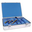
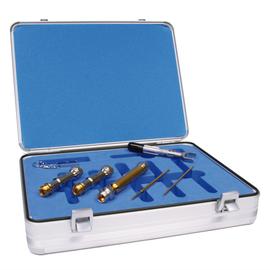
Verification kits help ensure that a vector network analyzer actually performs to its determined accuracy after being calibrated. With a Verification Kit DC-18 GHz N male to N female you get state-of-the-art measurement technology for your R&D, testing, and quality control department.
The set comes in a robust aluminum storage case and comprises two attenuators, one precision air line and additional accessories like calibration certificate, USB flash drive with calibration data and documentation, open end torque wrench AF 19 with torque setting 90 Ncm.
The Verification Kit DC-18 GHz N male to N female has a characteristic impedance of 50 Ω. It is characterised by low VSWR and insertion loss values as well as best intermodulation characteristics over the entire frequency range from DC to 18 GHz.
This product has gold-plated connections and is based on the better quality classes of the IEEE, ICE standards with regard to lower tolerances. SPINNER also uses the term ‘precision’ here to emphasize the suitability for exceptionally high-precision measurements.
The N-coaxial connectors were named after their inventor Paul Neill, who developed this standard for RF connectors in 1942. Often, however, the name also relates to the Navy Connector. Type N connectors can be used at frequencies up to 11 GHz, high-precision types up to 18 GHz. It is typically used in mobile communication applications with demanding mechanical and electrical requirements. SPINNER exclusively manufactures connectors with non-slotted outer conductor contacts and a special sealing profile in the connector head instead of the flat seal disk, specified by IEC or CECC. This ensures the most reliable sealing function.
SPINNER RF measurement components meet highest standards
SPINNER has set new standards of accuracy with this product line, which includes a large family of coaxial test equipment with outstanding electrical and mechanical attributes for use in laboratory and production environments.
For the production SPINNER applies extremely high standards regarding quality, engineering, materials and manufacturing e.g. DIN EN ISO 9001 - Quality Management, DIN EN ISO 14001 - Environmental Management and ISO 50001:2011 - Energy Management. This enables us to offer Verification Kits with the best possible performance and lowest possible intermodulation (Low PIM).