RF Switches with outstanding performance
A radio frequency (RF) switch plays a critical role in routing signals between different paths within the RF circuitry. Here’s a detailed breakdown of its function and importance:
- Signal Routing: RF switches enable the selection of different signal paths within a communication system. This routing function is essential for directing RF signals from one component to another, such as from a transmitter to an antenna or between different antenna elements.
- Frequency Band Selection: In mobile communication networks, RF switches allow the selection of different frequency bands. This capability is crucial for supporting multiple standards (e.g., GSM, LTE, 5G) and frequency bands in a single device. By switching between different frequency bands, a device can operate across various cellular networks and frequencies
- Antenna Switching: RF switches are used to switch between multiple antennas. For instance, in MIMO (Multiple Input Multiple Output) systems, RF switches manage the connections to different antennas to optimize signal strength and quality.
- Transmit/Receive (T/R) Switching: In transceivers, RF switches facilitate the switching between transmit and receive modes. This function is vital for time-division duplex (TDD) systems where the same frequency band is used for both transmitting and receiving but at different times.
- Redundancy and Fault Tolerance: In broadcasting systems, RF switches provide redundancy by switching to backup components or paths in case of failure. This ensures continuous operation and reliability of the communication system.
- Signal Testing and Monitoring: RF switches are often used in test and measurement setups to route signals to different test points or instruments without manually reconnecting cables. This allows for efficient and automated testing and monitoring of RF performance.
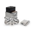
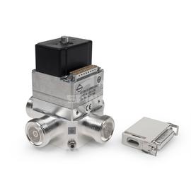
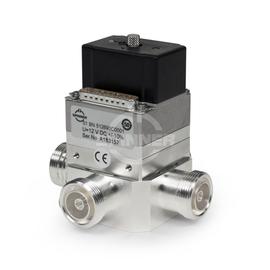
The Coaxial 2-way switch (DPDT) 2 kW DC-6 GHz 24 VDC 7-16 female ensures optimal performance for signal transmission between transmitter and antenna in broadcast stations.
Outstanding RF characteristics, best possible passive intermodulation and VSWR
The Coaxial 2-way switch (DPDT) 2 kW DC-6 GHz 24 VDC 7-16 female enables you to transmit high-frequency signals reliably and flawlessly with optimum protection of your sensitive equipment in a power range up to 2.0 kW @ DC to 1 GHz (at -10 to +45 °C ambient temperature), 1.4 kW @ 1 to 2 GHz (at -10 to +45 °C ambient temperature), 1.1 kW @ 2 to 3 GHz (at -10 to +45 °C ambient temperature), 1.0 kW @ 3 to 4 GHz (at -10 to +45 °C ambient temperature), 0.9 kW @ 4 to 5 GHz (at -10 to +45 °C ambient temperature), 0.8 kW @ 5 to 6 GHz (at -10 to +45 °C ambient temperature) with maximum passive intermodulation (IM3).
The protection class is IP 40.
The positive characteristics are briefly summarised: Fully compatible to BN 512690.
The 7-16 connector has become the most widely used coaxial connection system for mobile communication systems, due to its excellent mechanical and electrical properties. In order to achieve the industry leading intermodulation performance SPINNER applies silver-plating on all inner and outer conductor parts of the standard connector. As a supporting measure, we use exclusively non-magnetic materials, and we have minimized the number of RF contact points. The connection is especially suited for transmitting medium or high power indoors and outdoors.
Built-in switches use a hypocycloidic gear. This technology makes it possible to combine an extremely compact switch drive and a very short switching time. A sophisticated mechanical design guarantees that the auxiliary contacts (e. g. for a carrier safety loop) are actuated before opening and after closing the RF contacts. Thus, SPINNER switches reliably prevent accidental switching under load ('hot switching').
The drive and switch base (rotor) of a hypocycloid gear mechanism are connected by a special gear mechanism developed by SPINNER. This mechanism varies the torque and angular velocity across the switch’s rotational range. Initially, the torque is very high while the angular velocity of the switch rotor is very low. Then, as the angle increases the angular velocity steadily increases while the torque decreases. After passing the middle of the range, this is reversed and the angular velocity decreases while the torque increases. The drive mechanically locks in both end positions.
Due to the very compact dimensions and the high operational safety, SPINNER switches are preferably used in systems which must have a high level of reliability. The 2+1- and 4+1-switching units developed by Spinner provide an excellent solution to enable redundancy systems for interruption-free operation possible. With only one rack unit as 19" drawer, this compact switching system can maintain the broadcasting operations of remote stations despite the failure of a channel.
The switch offers the following advantages:
- low insertion loss and high isolation
- low VSWR over the whole frequency range
- short switching times and high reliability
- long service life up to 2 million switching cycles for switches with mechanical drive almost unlimited service life for switches with pin diodes
A solenoid drive, latching, self-cutoff actuator in a radio frequency (RF) switch operates by using a solenoid to move the switch's internal components. Here's how it works:
- Solenoid Drive: When an electrical current passes through the solenoid coil, it generates a magnetic field, moving a plunger or armature to engage or disengage the switch.
- Latching Mechanism: Once the solenoid moves the switch, a latching mechanism holds the switch in the new position without continuous power, which is energy-efficient.
- Self-Cutoff: After the switch is latched, the solenoid power is automatically cut off, preventing overheating and reducing power consumption.
This mechanism allows for precise and reliable switching in RF applications, ensuring minimal signal loss and stable operation over a wide frequency range.
A Double Pole Double Throw (DPDT) switch is an electrical switch that can control two separate circuits, allowing each to connect to one of two outputs. Essentially, it has two poles (each pole is a separate circuit) and two throws (two different output positions for each pole). This configuration enables the switch to route each input to one of two outputs, providing versatility in circuit control. DPDT switches are commonly used in applications requiring polarity reversal or the ability to switch between two different power sources.