SPINNER Filters offer reliability, performance, and value
Radio Frequency (RF) filters are crucial components in mobile communication and broadcast networks. Their primary function is to selectively allow signals of certain frequencies to pass while blocking others, thereby managing interference and enhancing the clarity and quality of the transmission. Applications include cellular base stations, broadcasting, and other RF communication systems.
Critical Characteristics and Success Factors:
- Selectivity: The ability to precisely isolate specific frequency bands.
- Insertion Loss: Minimal loss of signal strength through the filter.
- Power Handling: Capability to manage the power level of the signal without degradation.
- Durability: Performance consistency over a range of environmental conditions.
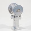
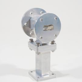
The Ortho mode transducer TX reject filter assembly UBR 120 is suitable for demanding applications with radio frequency signal transmission, e.g. in industry, satellite communications, radar or research facilities.
Outstanding RF characteristics, best possible passive intermodulation and VSWR
The Ortho mode transducer TX reject filter assembly UBR 120 enables you to transmit high-frequency signals reliably and flawlessly with optimum protection of your sensitive equipment in a power range up to Port 1: 200 W (TX port) with maximum passive intermodulation (IM3) of .
The protection class is IP 40.
The port path designation regarding main line and probe is as follows: Port 1: TX, Port 2: RX, Port 3: common
It supports the use following frequency bands : SHF
For interconnection of ordinary waveguides there exists a plurality of waveguide flanges. They are defined in detail by the standards IEC 60154-2, EIA RS-166, EIA RS-271, MIL-DTL-3922, MOD UK DEF-5352and others. These standards also specify the designations for the constructive flange design. The designation lists the type, e.g. flat flange without sealing groove, flat flange with sealing groove or choke flange with sealing groove. Furthermore, the types, i.e. the specific flange geometry (as in EIA and IEC standards) or the part number of a specific flange made of a specific material (as in MIL and DEF standards) are indicated. Finally, the designation of the waveguide is given.
For the specific details, please refer to the SPINNER technical document TD-00077. In addition to these standardized flange designs, there are other specific designs such as LIL (CERN), DESY or Merdinian. The compatibility is indicated in the data sheets.
Our RF filters are engineered with precision, offering exceptional selectivity and low insertion loss, which are critical for efficient RF communication. Our range includes filters designed for various specific applications, ensuring that whatever your needs, we have a filter that fits. With robust construction, our filters maintain performance across a broad range of environmental conditions, making them ideal for both mobile communication and broadcast networks.
Our unique approach to RF filter design combines innovative technology with practical application insights, resulting in products that not only meet but exceed industry standards. For anyone involved in the construction or operations of RF mobile communication or broadcast networks, our filters offer reliability, performance, and value.