SPINNER adapters offer outstanding electrical and mechanical properties
Adapters are used to connect transmission lines with different interface sizes (so-called inter-type or between-lines adapter) or within one size but different interface genders (so-called within-type or in-line adapter).
SPINNER high frequency adapters are optimized for quality and performance and are designed for the lowest possible reflection factors. The outstanding electrical and mechanical properties, the simple installation and the high reliability make SPINNER high-frequency adapters one of the most efficient and cost-effective transition connectors on the market. Precision adaptors with RF quality grade 0 are available upon request.
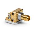
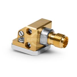
The SPINNER PCB launch connector 2.92 mm female DC-40 GHz
is characterized by its excellent low IM values and its longevity for test and measurement laboratories. A SPINNER precision adapter increases the lifetime of the connector of the analyzer considerably and thus saves money in the long term.
Outstanding RF characteristics, best possible passive intermodulation and VSWR
A PCB launch connector 2.92 mm female DC-40 GHz
enables you to reliably transmit radio-frequency signals in the frequency range from DC to 40 GHz.
The adaptor offers a transition from interface 2.92 mm female to interface 2.92 mm female. The right-angle connector enables installation in confined spaces or special cable inlets.
The 2.92 mm coaxial connector is a reliable connector system that works up to approx. 40 GHz and is used in RF measurement laboratories, on high power components, calibration and verification standards. It is also known as a Type-K connector. A 2.92 mm coax interface can be mechanically mated with 3.5 mm and SMA connector systems, but the connection creates a signal reflection that must be considered. It was the predecessor of the 1.85 mm connector size. Compared to the 3.5 mm connector system, the 2.92 mm interface has a shorter inner conductor pin that allows the outer conductor to be aligned before the inner conductor makes contact. Therefore, the 2.92 mm connector is less susceptible to damage in industrial use.