SPINNER Adapter bieten herausragende elektrische und mechanische Eigenschaften
Adapter werden verwendet, um Leitungselemente verschiedener Anschlussgrößen (sogenannte inter-type oder between-lines Adapter) oder innerhalb einer Größe, aber unterschiedlicher Anschlussgeschlechter miteinander zu verbinden (sogenannte within-type oder in-line Adapter). Als weitere übliche Bezeichnung für Adapter wird auch der Begriff Übergangsverbinder verwendet.
SPINNER Hochfrequenz-Übergangsverbinder sind auf Qualität und Leistung optimiert und so konstruiert, dass sie sehr niedrige Reflexionsfaktoren erzielen. Durch die herausragenden elektrischen und mechanischen Eigenschaften, die einfache Installation und die hohe Zuverlässigkeit zählen SPINNER Hochfrequenz Adapter zu den effizientesten und kosteneffektivsten Übergangsverbindern auf dem globalen Markt.
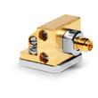
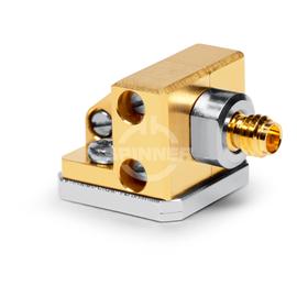
Der SPINNER Leiterplatten-Steckverbinder 1.0 mm Buchse DC-110 GHz zeichnet sich seine hervorragenden niedrigen IM-Werte und durch seine Langlebigkeit für Test- und Messanwendungen in Laboren aus. Ein SPINNER Präzisions-Übergangsverbinder erhöht die Lebensdauer der Messgeräte-Steckverbinder erheblich und spart damit langfristig Geld.
Hervorragende HF-Eigenschaften, bestmögliche passive Intermodulation und VSWR
Ein Leiterplatten-Steckverbinder 1.0 mm Buchse DC-110 GHz ermöglicht Ihnen eine verlässliche und einwandfreie Übertragung von Hochfrequenz-Signalen im Frequenzbereich von DC bis 110 GHz.
Der Adapter bietet einen Übergang von Anschluss 1.0 mm Buchse auf Anschluss 1.0 mm Buchse. Rechtwinklige Stecker ermöglichen zudem die Montage bei engen Bauräumen oder besonderen Kabelzuführungen.
1,0 mm-Koaxialsteckverbinder sind in HF-Laboren weltweit Standard und ein Muss für Ingenieure, die hochpräzise Messungen im Bereich bis 120 GHz durchführen. Dazu zählen u.a. Vektor-Netzwerk-Analysen (VNA) oder Messungen im Millimeter-Wellen-Bereich. Die koaxiale 1,0 mm Anschlussgröße ist auch als Typ-W-Stecker bekannt.